Speaker Placement and Acoustic Environment Effects
on Nearfield Monitor Systems –
MIX Magazine
To Woof Or Not To Woof? A SUBstantial Question – MIX Magazine
Optimizing the Studio Listening Environment – MIX Magazine
Acoustic Solutions, The RPG B.A.S.S. Trap – MIX Magazine
Examining the Yamaha NS-10M “Tissue Paper
Phenomenon” –
Recording Engineer/Producer Magazine
Sound Advice 1 – Modern Home Theater
Sound Advice 2 – Modern Home Theater
Sound Advice 3 – Modern Home Theater
Sound Advice 4 – Modern Home Theater
Sound Advice 5 – Modern Home Theater
Sound Advice 6 – Modern Home Theater
Sound Advice 7 – Modern Home Theater
Educational Resources
Articles written either for MIX
Magazine or Recording Engineer/
Producer Magazine or Modern
Home Theater.
– by Bob Hodas
Gain insights into studio listening environments and rooms.
Sound Advice 5
Modern Home Theater, December 2003 – by Bob Hodas
So, in the last article we had just gotten my speakers placed. Figure 1 shows the room layout once again. The five gray boxes are the L/C/R & Surrounds. The two black boxes are the LFE subs. The turquoise items in the lower right corner are my equipment racks. As stated in the last article, music is my primary focus. Therefore I have my discrete surrounds setup in the rear with the L/R/S in a modified equilateral setup. This follows the DTS recommendation more than the ITU, since most recording studios are not following the ITU recommendation to date. Remember that these are setup recommendations, not standards! I have also found (as have many engineers) that film soundtracks translate to discrete rears much better than 5.1 music translates to split surrounds or dipole/bipole style speakers. So if you want to listen to a lot of 5.1 music, my setup will work well for you. I should also mention that many studios that remix film soundtracks for DVD release use discrete rears as well (for instance, the award winning Mi Casa that remixes many of New Line’s releases).
So let’s look at the compromises that I needed to make in order to please the spousal factor and deal with the basic room design restrictions. For one, my rear speakers are at about 125 degrees instead of 120. This is because the entry way must be clear for walking. That wasn’t too bad since it still falls within the DTS limits. A big factor for me was the center speaker, which sat at the same height as my L/R. The center sat right in the middle of my picture window, blocking the fabulous view of the Golden Gate Bridge. That did not sit well with my S.O. She lived with it for months until I could no longer stand the pressure. Fortunately for me, when I tried measuring the speaker in a lower position, the frequency response was not any worse than on the tall stand, just different. Billy Bags made a perfect short speaker stand for this situation and so that issue was solved (fig. 2).
Lowering the center speaker also opened up another possibility. If you look carefully, on the left side of figure 2, you will see the edge of my plasma. Having the screen all the way to the left of the left speaker drove all of my film industry buddies nutso. That didn’t bother me, but they could never get over the dialog coming at them from the right, nor sitting on the couch at an angle to watch a DVD (see, I told you I am focused on music 5.1). With the center speaker lowered, I could now move the plasma to the ceiling above the window and lower it down right over the center speaker. My S.O. also really liked this and frankly since I made the change, I love it too. Dialog coming from the center of the screen, what a concept. It also freed up a lot of floor space that separated the kitchen and living room.
Now that the speakers were all in position, I turned my attention to some acoustic treatments. Since I have not yet discussed a method of finding those destructive first order reflections in previous articles, let’s do that now. First order reflections are the initial signal reflections that bounce off the walls, floor, and ceiling and mix in with the direct speaker signal. This delayed bounce will cause comb filtering (cancellations). The time delay and thus, frequency of interaction is dependent on the speaker distance from the walls. Additionally, if the left and right speakers are different distances from the walls, the cancellations will occur at different frequencies. In most homes the reflections will be short enough that your brain cannot separate them out from the direct signal. These destructive reflections cause holes in the frequency response so you miss parts of the music. They also affect the phase response, so it creates problems in the soundstage and imaging, both side-to-side and front to back. The bit on coffee tables in Sound Advice 3 has a figure that shows what this is all about.
Sound and light act a lot alike above 400Hz, so you can use a mirror and simple geometry to find these unwanted reflections. Invest about $30 in a 2’ x 2’ plastic mirror (no frame). You can get one at a plastics store. Have someone sit in the listening position while you hold the mirror absolutely flat against the sidewalls and ceiling. Slide the mirror all around to see if the listener can see the speaker components (not the side or top of the speakers) in the mirror. Every time the speaker is seen in the mirror, that is a first order reflection point. You will want to put a treatment in that place. Remember that you must keep the mirror perfectly against the boundary surface while doing this test. It’s just like billiards; the geometry needs to be exact. You will probably be able to outline one large area on the sidewalls that shows the reflection of all three front speakers.
I like to absorb the ceiling and side reflections because this increases the coherence of the system. Coherence is very important for imaging. I like to diffuse the rear wall reflections because it adds space to the room. The diffusion gets rid of the discrete reflection but leaves most of the energy intact. The energy is just spread out over time. Don't let anyone try to equalize first order reflections as they are completely dependent on your position and will change at different seating positions throughout the room. Equalization will not fix a high frequency reflection problem.
Take a look at figures 3 & 4. I built a simple panel for my ceiling reflection out of 1/2” soundboard with 1” compressed fiberglass glued to it. Then I wrapped the panel in some acoustically transparent material and stuck it in the ceiling. I mounted it to the underside of the beams instead of directly on the ceiling, because with an airspace between the panel and the ceiling, it becomes more effective at lower frequencies. I like to make my panels a bit bigger than the area the mirror shows because people tend to shift around. On the rear wall, the nice fireplace was a bit too lively. I used an RPG panel that does both absorption and diffusion and it took care of all of the problems. Because I have honeycomb shades on the window on the right side, the shades worked as the reflection treatment. The left side reflection doesn’t exist because there is no wall between the living room and kitchen where the reflection would occur. Figure 5 is the modified room front.
Some people don’t really want these styles of treatments in their living spaces and I can understand that. There are alternatives out there. A wall sculpture could replace a diffusor for instance. Or how about just an artsy wood thingy. I’ve seen some great carved wooden panels from Thailand and China that could fill the bill. It won’t be a scientific series of reflections but hey, it could break up the wavefront. Another trick I like is to use a tapestry or wall hanging as an absorber. In fact you could even hide an absorptive panel behind a tapestry. Heavy curtains will of course do the trick but don’t have a nonpourus back on them.
Once again I’ve run out of article space so this will have to continue on next time. We will finish up my room by discussing equalization and how I applied it to tweak out the system.
Happy Holidays to all from HoHo Hodas
Figures:
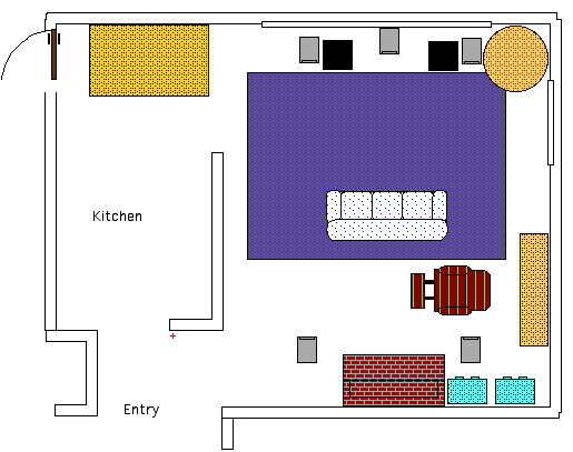
Fig. 1 Room layout

Fig. 2 Front of room
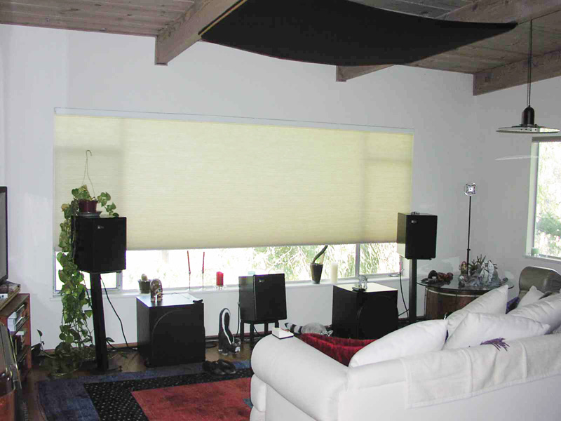
Fig. 3 Ceiling panel

Fig. 4 Rear wall panel
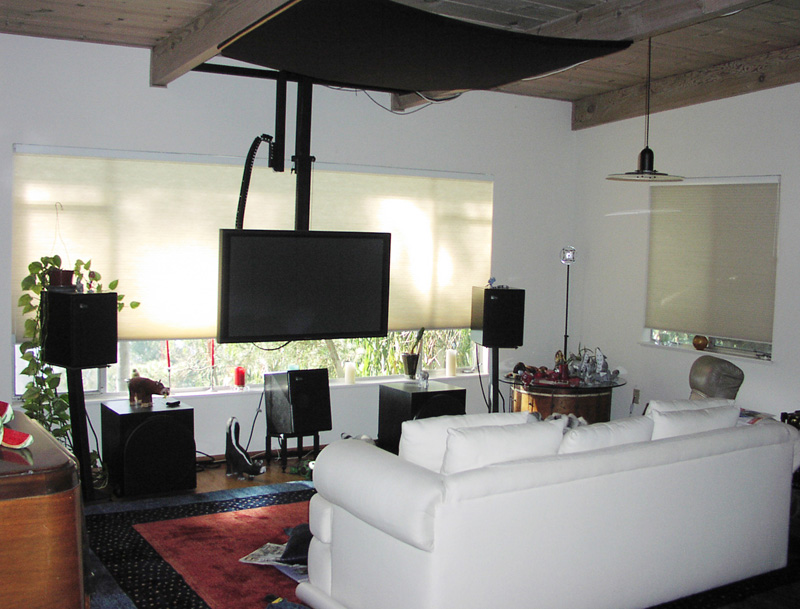
Fig. 5 Finished front of room